

Cylinder Designs
To provide you with an overview of the many possible applications, the following table displays the function and design of hydraulic cylinder designs.
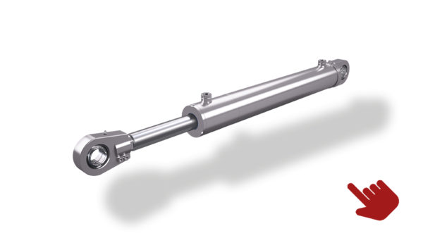
Plunger Cylinder
This single-action cylinder is pressurized only in one direction and returns through its own weight. Plunger cylinders are also available with an upper limit stop.
Application: Pressen, Baumaschinen, Schwerfahrzeugbau
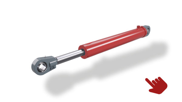
Single-Action Cylinder
According to pressurization of the piston area, this cylinder may be either a pressure or a traction cylinder. The unpressurized piston side has an air filter to prevent dust from penetrating into the cylinder, reducing wear. If a spring has been provided as reset force, the spring pretension must be determined.
Single-Acting Telescopic Cylinder
Telescopic cylinders are adapted to limited installation space and, at the same time, fulfill the requirement for the longest stroke possible. All stages of the cylinder are pressurized on one side and the cylinder releases its power during extension. The cylinder retracts through its own weight.
Application: Fahrzeug-, Bagger- und Maschinenbau usw.
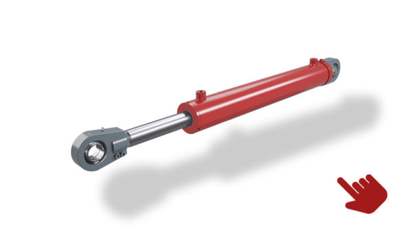
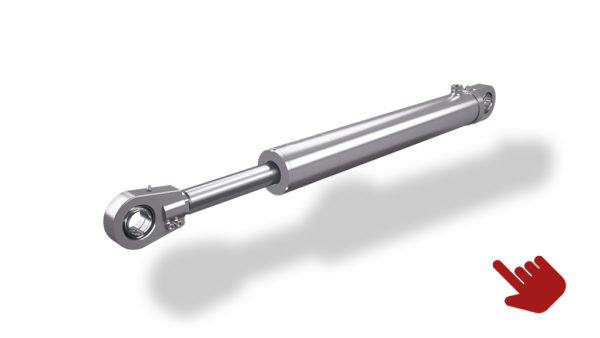
Double-Action Cylinder (Differential Cylinder)
These cylinders are the most commonly used hydraulic cylinders. They can be manufactured with damping on the piston or rod side or on both sides.
In the case of this model, a force can be transmitted in both directions of movement. They are called differential cylinders because the piston area and the piston rod area differ and thus the cylinder extends slowly and retracts comparatively quickly at a constant feed flow.
Double-Action Telescopic Cylinder
This telescopic cylinder can act in both directions.
Application: Feed mechanism for large furnaces and brick kilns
Hydraulic Cylinder Dimensions
When you select a hydraulic cylinder, the determination of the amount of operating pressure is vitally important. Together with the forces and the stroke speeds required for the task, the operating pressure determines the cylinder sizes and thus the costs.
Force and Movement Ratios of a Double-Action Cylinder
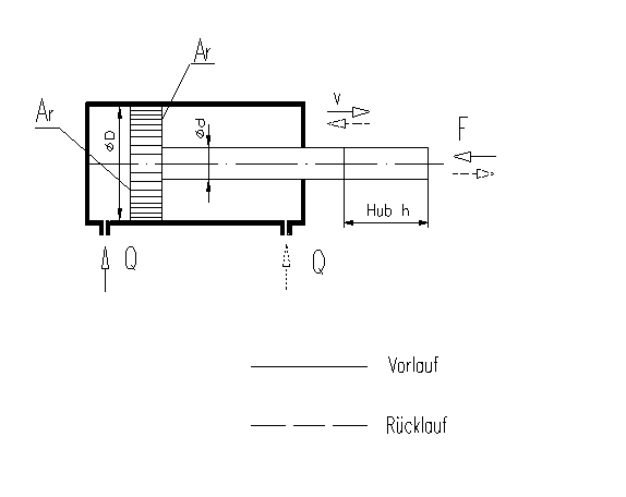
If an external force F acts on a piston, this force creates a pressure on the piston area Ak. Conversely, this force is also a resistance that the pump delivery Q meets. In this way, a pressure builds that acts evenly on all sides, including the piston area Ak. The piston can thus now exert a force itself according to the following formula:
F = p * Ar (analogously for the return)
| F | = | Piston Force | in [N] | |
|---|---|---|---|---|
| Ak | = | Piston area | (D² *3,14) 4 | in [mm²] |
| Ar | = | Piston ring area | (D²-d²) * 3,14 4 | in [mm²] |
| D | = | Piston diameter | in [mm] | |
| d | = | Rod diameter | in [mm] | |
| h | = | Travel length | in [mm] | |
| Q | = | Feed flow | in [l/min] | |
| t | = | Travel time | in [s] | |
| v | = | Travel speed | in [m/s] |
Piston Speeds
The feed flow or return flow speeds are calculated using the flows of liquid coming from the pump, which fill the stroke volume of the hydraulic cylinder within a certain unit of time.
For the speeds specified above, the following equations result under consideration of the usual units:
| v | = | Q Ak | Extension |
| v | = | Q Ar | Retraction |
Please observe that the volume of liquid flowing away during the return flow is always greater than the inflowing liquid due to the difference in area. As a result, the return flow is faster than the feed flow. If the length of the cylinder stroke is known, the stroke time t can be calculated as follows.
| t | = | Ak * h Q | Extension |
| t | = | Ar * h Q | Retraction |
Buckling Strength of the Piston Rods
The danger of the piston rods buckling during long strokes and an additional unfavorable cylinder mounting determine the cylinder sizes and their limits.
The calculations are usually carried out according to Euler since the piston rods are to be seen as slender rods.
The following applies:
| Fk | = | 3,14² * E * I Lk² |
| FK | = | Force at which the piston rod buckles | in [N] |
|---|---|---|---|
| E | = | Modulus of elasticity (Steel 210.000 N/mm²) | in [N/mm2] |
| I | = | Moment of inertia (for circle cross-section) | in [mm4] |
| LK | = | Free buckling length | in [mm4] |
The following diagram shows the four so-called Eulerian load cases. The permissible stroke lengths of every hydraulic cylinder series are listed in the appendix.
End Position Damping
In the case of end position damping, the kinetic energy is converted to heat energy. At a constant delay, the following applies:
m 2 | v² | = A * p * s (conservation of energy) |
| m | = | moving mass | (kg) |
|---|---|---|---|
| v | = | Travel speed | [m/s] |
| A | = | Effective damping area | [m²] |
| p | = | Average damping pressure | N m² |
| s | = | Damping distance | [m] |