Connecting Bore
Guide and Seal
Cylindrical forces and buckling
Connecting Bore
Connecting Bore
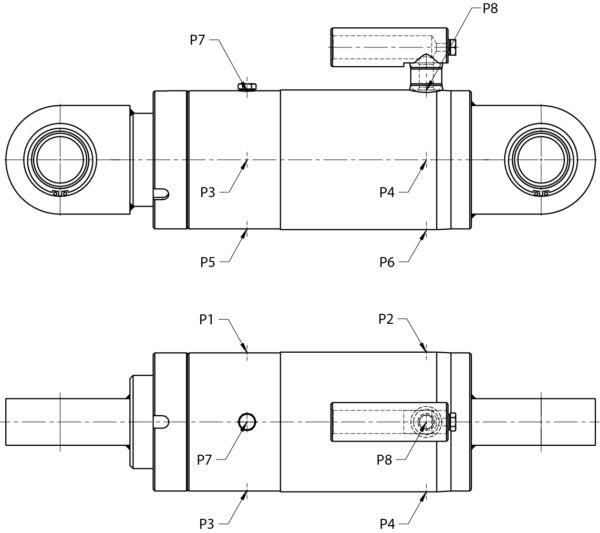
The connection hole is located at the bottom end of the cylinder and is designed for line break valves.
The position on the circumference can be changed (standard P8).
Drawing of the position of the vents P7 and the connection piece P8
Guide and Seal
For long strokes, the support width of the piston rod in the cylinder tube can be changed in order to reduce the load on the guide system when fully extended. This also depends on the type of installation and the design of the cylinder.

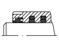
D1 - Groove ring and scraper made of polyurethan (standard) | |
|---|---|
| Temperature range | -30°C to +80°C |
| Hydraulic fluid | Mineral oil |
| Stroke speed | ≤ 0,5 m/s |
| Application | Standard seal set for normal operating conditions, offers very high resistance to wear |
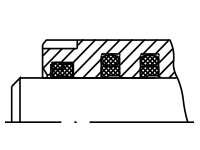
D2 - Axial seal ring set consisting of PTFE STEP SEALS (O-ring seal made of NBR) - double scraper (polyurethane) | |
|---|---|
| Temperature range | -30°C to +100°C |
| Hydraulic fluid | Mineral oil, flame-retardant hydraulic fluids HFA and HFB up to +40°C; HFC up to +60°C |
| Stroke speed | ≤ 1 m/s |
| Application | Seal set for high sliding speeds, no stick-slip effect, higher leakage compared to D1 and D3 |
D2V - Axial seal ring set consisting of PTFE STEP SEALS (O-ring seal made of Viton)Double scraper (Viton O-ring seals) | |
|---|---|
| Application | Sealing set for high sliding speeds, no stick-slip effect, greater leakage than in the case of D1 and D3, for higher temperatures (+200°C) and fluids on a phosphate ester basis (HFD) |

D3 - Tandem sealing set consisting of groove ring (polyurethane) and PTFE STEP SEAL | |
|---|---|
| Temperature range | -30°C to +80°C |
| Hydraulic fluid | Mineral oil |
| Stroke speed | ≤ 0,8 m/s |
| Application | Sealing set for high loads at minimum leakage, smooth-running stroke movements |
Cylindrical forces and buckling
Theoretical cylinder force in [kN] (efficiency = 100%)
Rod Ø [mm] | Piston Area [mm²] | Operating Pressure [bar] | |||
|---|---|---|---|---|---|
| 50 | 100 | 160 | |||
| 40 | 1256,6 | 6,3 | 12,6 | 20,1 | |
| 50 | 1963,5 | 9,8 | 19,6 | 31,4 | |
| 60 | 2827,4 | 14,1 | 28,3 | 45,2 | |
| 70 | 3848,5 | 19,2 | 38,5 | 61,6 | |
| 80 | 5026,5 | 25,1 | 50,3 | 80,4 | |
| 90 | 6361,7 | 31,8 | 63,6 | 101,8 | |
| 100 | 7854,0 | 39,3 | 78,5 | 125,7 | |
Knickung
Grundlagen siehe >>Technische Grundlagen
Tabelle: zulässige Hübe (im elastischen Bereich) in mm // Knicksicherheit Sk=3,5
