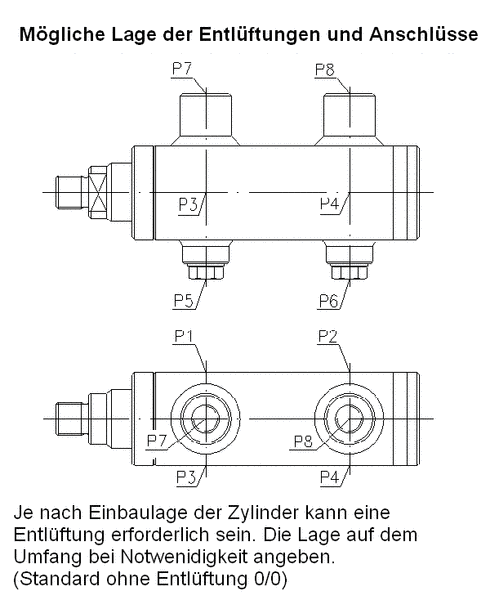
The pipe thread of the connecting bore is designed according to ISO 228/1. The position along the perimeter can be changed (Standard P7/P8).
For long strokes, the support width of the piston rod in the cylinder tube can be changed in order to reduce the load on the guide system when fully extended. This also depends on the type of installation and the design of the cylinder.
D1 - Groove ring and scraper made of polyurethane and a compact seal (NBR) on the piston (standard) | |
|---|---|
| Temperature range | -30°C to +80°C |
| Hydraulic fluid | Mineral oil |
| Stroke speed | ≤ 0,5 m/s |
| Application | Standard seal set for normal operating conditions, offers very high resistance to wear |
D2 - Axial seal ring set consisting of PTFE STEP SEALS (O-ring seal made of NBR), double scraper (polyurethane) and a PTFE Glyd ring (NBR O ring seal) on the piston | |
|---|---|
| Temperature range | -30°C to +100°C |
| Hydraulic fluid | Mineral oil, flame-retardant hydraulic fluids HFA and HFB up to +40°C |
| Stroke speed | ≤ 1 m/s |
| Application | Seal set for high sliding speeds, no stick-slip effect, higher leakage compared to D1 and D3 |
D2V - Axial seal ring set consisting of PTFE STEP SEALS (O-ring seal made of Viton) Double scraper(Viton O-ring seals) and a PTFE Glyd ring (Viton O ring seal) on the piston | |
|---|---|
| Application | Sealing set for high sliding speeds, no stick-slip effect, greater leakage than in the case of D1 and D3, for higher temperatures (+200°C) and fluids on a phosphate ester basis (HFD) |
D3 - Tandem sealing set consisting of groove ring (polyurethane) and PTFE STEP SEAL and a compact seal (NBR-PTFE) on the piston | |
|---|---|
| Temperature range | -30°C to +80°C |
| Hydraulic fluid | Mineral oil |
| Stroke speed | ≤ 0,8 m/s |
| Application | Sealing set for high loads at minimum leakage, smooth-running stroke movements |
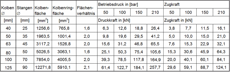
Theoretical cylinder force in [kN] (efficiency = 100%)
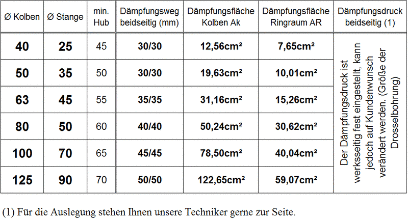
Die Endlagendämpfung gewährleistet ein weiches Abbremsen der Hubgeschwindigkeit des Hydraulikzylinders in den beiden Endlagen. Die Dämpfung wird erreicht durch eine Drosselung des Flüssigkeitsstromes, wobei die aus der Bewegung sich ergebende kinetische Energie in Wärme umgewandelt wird.Die kinetische Energie E als Produkt aller auf die Kolbenstange wirkenden Massen m und der Hubdeschwindigkeit v bei Dämfungsbeginn, darf das Arbeitsvermögen W der Dämpfung nicht überschreiten.
Ausfahrbewegung
| FB = m x a + AK x p | FB [N] | = | Bremskraft |
| m [kg] | = | moving mass | |
| AK [cm²] | = | Piston area | |
| p [N/cm²] | = | Systemdruck | |
| v [m/s] | = | Stroke speed | |
| s [m] | = | Damping distance | |
| a [m/s²] | = | Verzögerung | |
| a [m/s²] | a=v²/2s |
Einfahrbewegung
| FB = m x a + AR x p | FB [N] | = | Bremskraft |
| m [kg] | = | moving mass | |
| AK [cm²] | = | Piston area | |
| p [N/cm²] | = | Systemdruck | |
| v [m/s] | = | Stroke speed | |
| s [m] | = | Damping distance | |
| a [m/s²] | = | Verzögerung | |
| a [m/s²] | = | 1 bar ~ 10 |
Für den vertikalen Einbau muß zur Bremskraft FB noch die Gewichtskraft der äußeren Last und der Kolbenstange addiert bzw. subtrahiert werden.Die Zylinderreibung wird bei Berechnung vernachlässigt.
Berechnung des mittleren Dämpfungsdrucks
| PD = FB/AD | PD [N/ cm²] | = | Average damping pressure |
| FB [N] | = | Bremskraft | |
| AD [cm²] | = | Piston area | |
| 1 bar ~ 10 |
Bei einem zu hohen mittleren Dämpfungsdruck muss entweder die Dämpfungslänge oder der Systemdruck verringert werden.