Single-Action Hydraulic Cylinder
up to 250 bar // HZE5
General Information
The cylinders in the HZE5 series are single-acting pressure cylinders that can be used universally thanks to their different designs and sealing variants. The piston rod is made of high-strength structural steel with a hard chrome coating of approx. 25μm. Other materials and coatings are available on request. The piston rod end is guided in the cylinder tube, which minimizes wear on the piston rod guide and the seal. For lateral forces and non-vertical installation, please contact us.
Technical Information |
|
|---|---|
| Maximal operating pressure | = 250 bar |
| Testing pressure | = 315 bar |
| Rod Ø | = 50 – 150 mm |
| Accepted temperature range of the hydraulic fluid | = -20°C up to +80°C |
| Hydraulic fluid | = mineral oil (HL, HLP) according to DIN 51524 & DIN 51525 (standard) |
| Stroke speed | = ≤ 0,5 m/s (Standard) |
Length and stroke tolerances according to DIN7168g (see >>Technical Information)
Mounting Type |
Data Sheet | ||
|---|---|---|---|
| A | Base-side ball-and-socket joint | (DO – Standard) | >> Bauform-A |
| E | Rod-side Trunnion | >> Bauform-E | |
| F | Rod-side flange | >> Bauform-F | |
| H | beiseitiges Gelenklager | (DO – Standard) | >> Bauform-H |
Accessories |
Data Sheet | ||
|---|---|---|---|
| A-.. | Rod clevis | (GE-DO subject to maintenance) | >> Gelenkkopf-A |
| B-.. | Rod clevis | (GE..HO wartungspflichtig) | >> Gelenkkopf-B |
| G-.. | Gabelkopf | (Tolerance field H11) | >> Gelenkkopf-B |
Additional Information
Order Key
Click >> this link to download the order key in PDF format.
Connecting Bore
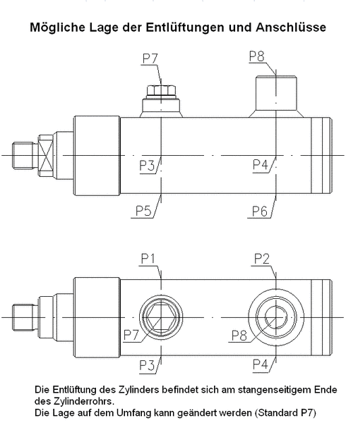
The connection hole is located at the bottom end of the cylinder and is designed for line break valves.
The position on the circumference can be changed (standard P8).
Drawing of the position of the vents P7 and the connection piece P8
Threaded Connection | Line Break Safety Device | Brake Valve | ||
|---|---|---|---|---|
| Height | Thread depth | Height | Thread depth | |
| G1/4″ | 40 | 32 | 55 | 32 |
| G3/8″ | 50 | 35 | 60 | 34 |
| G1/2″ | 55 | 44 | 70 | 40 |
| G3/4″ | 65 | 51 | 80 | 51 |

For long strokes, the support width of the piston rod in the cylinder tube can be changed in order to reduce the load on the guide system when fully extended. This also depends on the type of installation and the design of the cylinder.

D1 - Groove ring and scraper made of polyurethan (standard) | |
|---|---|
| Temperature range | -30°C to +80°C |
| Hydraulic fluid | Mineral oil |
| Stroke speed | ≤ 0,5 m/s |
| Application | Standard seal set for normal operating conditions, offers very high resistance to wear |

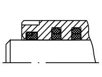
D2 - Axial seal ring set consisting of PTFE STEP SEALS (O-ring seal made of NBR) - double scraper (polyurethane) | |
|---|---|
| Temperature range | -30°C to +100°C |
| Hydraulic fluid | Mineral oil, flame-retardant hydraulic fluids HFA and HFB up to +40°C; HFC up to +60°C |
| Stroke speed | ≤ 1 m/s |
| Application | Seal set for high sliding speeds, no stick-slip effect, higher leakage compared to D1 and D3 |

D2V - Axial seal ring set consisting of PTFE STEP SEALS (O-ring seal made of Viton)Double scraper (Viton O-ring seals) | |
|---|---|
| Application | Sealing set for high sliding speeds, no stick-slip effect, greater leakage than in the case of D1 and D3, for higher temperatures (+200°C) and fluids on a phosphate ester basis (HFD) |

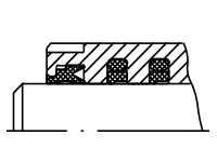
D3 - Tandem sealing set consisting of groove ring (polyurethane) and PTFE STEP SEAL | |
|---|---|
| Temperature range | -30°C to +80°C |
| Hydraulic fluid | Mineral oil |
| Stroke speed | ≤ 0,8 m/s |
| Application | Sealing set for high loads at minimum leakage, smooth-running stroke movements |
Theoretical cylinder force in [kN] (efficiency = 100%)
Rod Ø [mm] | Piston Area [mm²] | Operating Pressure [bar] | ||||
|---|---|---|---|---|---|---|
| 50 | 100 | 150 | 200 | 250 | ||
| 50 | 1963,5 | 9,8 | 19,6 | 29,5 | 39,9 | 49,1 |
| 60 | 2827,4 | 14,1 | 28,3 | 42,4 | 56,5 | 70,7 |
| 70 | 3848,5 | 19,2 | 38,5 | 57,7 | 77,0 | 96,2 |
| 80 | 5026,5 | 25,1 | 50,3 | 75,4 | 100,5 | 125,7 |
| 90 | 6361,7 | 31,8 | 63,6 | 95,4 | 127,2 | 159,0 |
| 100 | 7854,0 | 39,3 | 78,5 | 117,8 | 157,1 | 196,3 |
| 110 | 9503,3 | 47,5 | 95,0 | 142,5 | 190,1 | 237,5 |
| 120 | 11309,7 | 56,5 | 113,1 | 169,6 | 226,2 | 282,7 |
| 130 | 13273,2 | 66,4 | 132,7 | 199,1 | 265,5 | 331,8 |
| 140 | 15393,8 | 77,0 | 153,9 | 230,9 | 307,9 | 384,8 |
| 150 | 17671,5 | 88,4 | 176,7 | 265,1 | 353,4 | 441,8 |
